New FD in Town!

-
chickenwafer
- Posts: 2515
- Joined: Wed Mar 11, 2009 9:14
- Location: Greeley
speedjunkie wrote:This is arguable. It depends on what you're trying to get a read on more...the temp coming out of your IC or the temp going into the combustion chamber lol. If you want to see what the temps are right out of your IC, then the elbow would be better than right over the engine. But if you want to see the temps just before it enters the combustion chamber, the stock location would be more accurate I would think.
VRx8 wrote:Heat soak is a big problem on the stock location
Eduardo pretty much summed it up lol. The stock location won't be as accurate because of heat radiating from the engine, not to mention the stock UIM heat soaking and effecting the sensor giving more inaccurate readings.
If the UIM was sheet metal aluminum or plastic it would probably work better and give more accurate temps. I still left mine in the UIM but I may move it or add a second one with the factory fuel temp sensor circuit.

-
speedjunkie

- Senior Member
- Posts: 5359
- Joined: Wed Jan 02, 2008 9:14
- Location: Colorado Springs
- Contact:
Yeah, I get that. And that's what I'm saying. You're lying to yourself if you think the air is as cold going into the engine as it would be reading at the elbow. If you're just saying that the heat is affecting the sensor by making it mess up, then I agree. But if we're just talking about it reading hotter temps...yeah, because the air will be hotter because of heatsoak. And even so, isn't the aftermarket sensor plastic anyway? The threads anyway.

-
speedjunkie
- Senior Member
- Posts: 5359
- Joined: Wed Jan 02, 2008 9:14
- Location: Colorado Springs
- Contact:
-
chickenwafer
- Posts: 2515
- Joined: Wed Mar 11, 2009 9:14
- Location: Greeley
So Sleeper7 (chuck) came by today and did some tuning. Showed me some IN's and OUT's of the Haltech.
I also asked him about the AIT sensor and he told me it doesn't matter if you put the AIT sensor before or after the nozzle. If I have the correction table set to 0 is not going to add fuel regardless the AIT reading.
I also asked him about the AIT sensor and he told me it doesn't matter if you put the AIT sensor before or after the nozzle. If I have the correction table set to 0 is not going to add fuel regardless the AIT reading.
-
chickenwafer
- Posts: 2515
- Joined: Wed Mar 11, 2009 9:14
- Location: Greeley
Correct, if your compensation table is set to 0 it will obviously do nothing because there is no correction factor. I would stress that having your AIT sensor correction set to 0 is absolutely overlooking a critical sensor and will make your tune very inconsistent based on weather changes.
It's fine to have it set to 0 for initial tuning, but you will want to adjust the values once you're initial tuning is complete. So in the end, nozzle placement should have an effect on your tune, like how I outlined earlier.
Intake temperature compensation correction factors are often one of the most overlooked and misunderstood aspects when setting up a tune and it takes a while to nail it down. But when done right your tune should have very consistent AFRs regardless of temperature.
So non bose carpets are getting hard to find and you can have them made for $100+. Not like is extremely expensive but If you can save a couple bucks why not right?
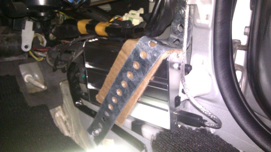
Well Im making a panel for the rear hatch. Plan is to make it fold and give me access to the fuel pump and spare tire.
Here is where Im at
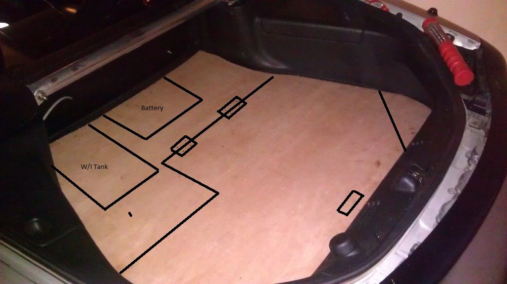
Just need some black carpet, adhesive spray, foam sheets and some hinges
Well Im making a panel for the rear hatch. Plan is to make it fold and give me access to the fuel pump and spare tire.
Here is where Im at
Just need some black carpet, adhesive spray, foam sheets and some hinges
-
speedjunkie
- Senior Member
- Posts: 5359
- Joined: Wed Jan 02, 2008 9:14
- Location: Colorado Springs
- Contact:
Are you cutting in two pieces and having the rear part fold up? If so, think about the rear corners of the hatch, the upper part is further inward than the bottom, so it probably won't clear that part. I know this because I was going to do the exact same thing LOL. Also, do you still have the spare tire?
Is that made of wood or what? It looks like wood but I can't really tell.
Is that made of wood or what? It looks like wood but I can't really tell.
Yeap 1/8 plywood, Im going to cut the bottom corners diagonal and put a hinge so when I raise the panel, the corners fold downwards clearing the upper part.
Im keeping the spare back there. I'll take it out when i go to the track but thats it.
I updated the pic, like that. On the corner the hinge goes under.
Im keeping the spare back there. I'll take it out when i go to the track but thats it.
I updated the pic, like that. On the corner the hinge goes under.
-
speedjunkie
- Senior Member
- Posts: 5359
- Joined: Wed Jan 02, 2008 9:14
- Location: Colorado Springs
- Contact:
Who is online
Users browsing this forum: No registered users and 126 guests