What turbo you pick for your car has a direct correlation on how much enjoyment you will receive from it. No one wants to wait through 2/3rd of the powerband for a turbo to spool, and on the other side of the spectrum no one wants a turbo that doesn't flow enough power for their goals and needs.
OEM manufactures realize this, and that is why OEM turbo system have turbos that spool within the first 1/3rd of their powerband, because this is where you spend the most of your driving. Not many people, aside from time attack road racers, spend any serious time near redline.
So first, we need to figure out how much airflow you require. There is a rather simple formula to figure this out, and you only need to do it once (for each boost pressure), then you can plot the figure on various compressor maps.
Pressure Ratio
First, complete the following equation to figure out your Pressure Ratio (PR). Pressure Ratio is defined as absolute outlet air pressure divided by absolute inlet air pressure. This formula is the only you will need to keep figuring if you want to change boost levels. There are a few different variables in here why we use the numbers we do, but without getting into the Ideal Gas Law, we can just use these numbers.
14.7 + Boost Pressure/14.7
For example:
14.7+ 15psi = 29.7/14.7 = 2.0 PR (Round to the nearest tenth)
The 14.7 represents ambient air pressure. Of course, at our altitude, we don't have this much air pressure. At 5000ft, we have 12.4psi of ambient air pressure. So, a more accurate way to calculate this would be the following formula:
12.4+ Boost Pressure/12.4
An example:
12.4+ 15psi = 27.4/12.4 = 2.2 PR (Rounded to the nearest tenth)
As we can cleary see, our pressure ratio is 0.2 higher than without accounting for altitude (which is a good deal). This points out why our turbos need to flow MORE air for a given PSI than at sea level, so they are working harder for a same pressure level than a turbo would be at sea level.
Also, if you have a lot of intake piping, such as a cold air intake with a filter and a large air box, you should also deduct another 1 PSIA from your absolute ambient air pressure. In our scenario, this would mean 12.4psia now becomes 11.4psia. This is to account of for restriction of your intake. You don't have to do this (I'm not in this example), but it will give you a more accurate PR.
Just a quick example, I will not use this again:
12.4 + 15psi =27.4/12.4-1= 2.4 PR
Now, we use the newly figured out Pressure Ratio (the Y axis on the compressor map) to figure out how much airflow you need for your desired boost level. To do this, we need some more information. So plug in the following formula:
(Displacement) (RPM) (Volumetric Efficiency) (Pressure Ratio)/5660
Displacement is easy, use your displacement in liters rounded to the nearest tenth. A Mazdaspeed3/6 would obviously be 2.3. For a rotary, we have to convert to piston math, so a 13B is 2.6L, a 12A is 2.4L, 20B is 4L.
RPM is the redline of your motor. Even if your motor doesn't make power all the way to redline, you need to plug in the highest RPM you're going to see, because even if power doesn't increase with RPM, airflow does. If your redline is 6000rpm, but you don't rev past 5500rpm, then plug in 5500rpm.
Volumetric efficiency is simply because no system is 100% efficient. For most systems, 90% is acceptable for Rotaries, 92-95% for 4-valve piston motors. To input this into the formula, enter it as a whole number, so 90% is entered as 90 (not 0.9).
Finally, the pressure ratio (PR) is the number we just figured out, which is boost-dependent, so it changes depending on what boost and RPM you want to run.
So, for example on a 13B-REW:
(2.6L) (8000rpm) (90%VE) (2.2)/5660 = 727.6
The number we just received is our CFM (Cubic Feet per Minute), which is a volume measurement of a gas, in this case, air.
So now we have an air flow requirement of 727.6 CFM. So what? Of course, turbo compressor maps have air flow in LBS per Minute (Lbs/min) on the X axis. So now, we need to complete yet another conversion to get our CFM into lbs/min.
Formula:
(CFM) (0.069) = lbs/min
And our example:
(727.6) (0.069) = 50.2 lbs/min
One quick way we can calculate power is 1 lb/min of airflow is equal to about 10rwhp. So, for 50.2lbs/min of air, this should be 502rwhp. This is just a ballpark, but it should get you close. Rotaries require more airflow per horsepower than piston motors, so for rotaries the forumla is 7.69 rwhp per 1 lb of airflow per minute. So in our example this would be 386rwhp. This is why turbo sizing for rotaries is so different, and why rotaries seemingly run larger turbos for less power. If you rotary is streetported, add 10% for the horsepower calculator. Bridgeports can add 16-18%.
To take this method one step further and to compensate for our altitude, we loose about 10% power up here. For the 10rwhp per 1/lbs of air in piston math and 7.69rwhp per 1lb of air for rotaries doesn't hold true up here, it's 10% LESS. So 1lb of air is 9rwhp for pistons and 1lbs of air is 6.92rwhp for rotaries. Or just figure your horsepower number using normal math and then subtract 10%.
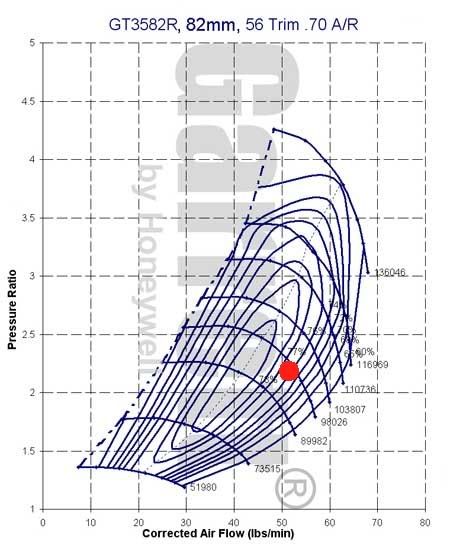
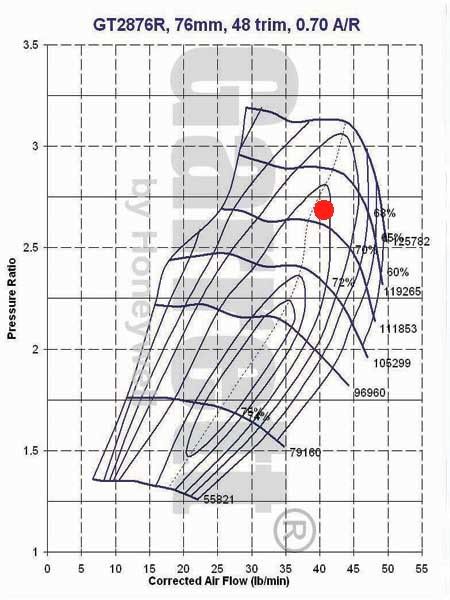
And now these are the numbers we use to plot on our compressor map. The vertical axis/y axis is the Pressure Ratio, which in our example is 2.2. The horizontal axis/X axis is in lbs/min.
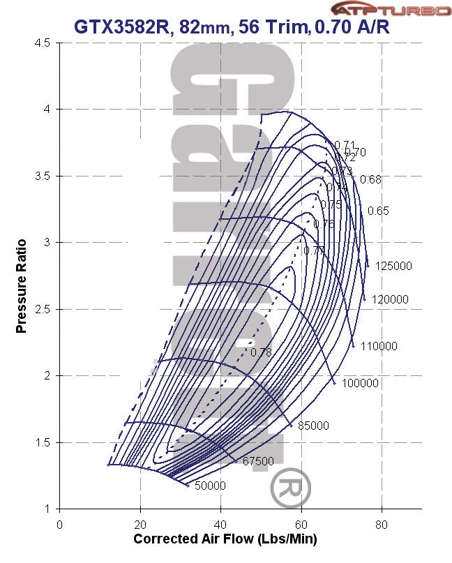
On the compressor map, there are what we can "efficiency islands". The turbo is most efficient in the center of the map. Think of the map as a geographical topographry map, with the center efficiency island being the highest point (like a mountain), and the map getting smaller as it spreads out. You want to be as close to the center as possible on the map to be in the best efficiency range. Too far to the left of the map and you will surge (the turbo is pumping more air than the engine can ingest), and too far to the right and the turbo will become a restriction and starve your motor, also known as the choke line.
So now, let's plot what we just did in our example on a Garrett GT3582R compressor map. The PR is 2.2 and the lbs/min is 50.2 (or 50lbs/min):